Hardware
Identifying your serial interface
You can determine if you have an I2C or a SPI interface by counting the number of pins on your card. An I2C display will have 4 pins while an SPI interface will have 6 or 7 pins.
If you have a SPI display, check the back of your display for a configuration such as this:
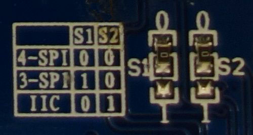
For this display, the two 0 Ohm (jumper) resistors have been connected to “0” and the table shows that “0 0” is 4-wire SPI. That is the type of connection that is currently supported by the SPI mode of this library.
A list of tested devices can be found in the wiki.
I2C vs. SPI
If you have not yet purchased your display, you may be wondering if you should get an I2C or SPI display. The basic trade-off is that I2C will be easier to connect because it has fewer pins while SPI may have a faster display update rate due to running at a higher frequency and having less overhead (see benchmarks).
Tips for connecting the display
- If you don’t want to solder directly on the Pi, get 2.54mm 40 pin female single row headers, cut them to length, push them onto the Pi pins, then solder wires to the headers.
- If you need to remove existing pins to connect wires, be careful to heat each pin thoroughly, or circuit board traces may be broken.
- Triple check your connections. In particular, do not reverse VCC and GND.
Pre-requisites
I2C
The P1 header pins should be connected as follows:
| OLED Pin | Name | Remarks | RPi Pin | RPi Function |
|---|---|---|---|---|
| 1 | GND | Ground | P01-6 | GND |
| 2 | VCC | +3.3V Power | P01-1 | 3V3 |
| 3 | SCL | Clock | P01-5 | GPIO 3 (SCL) |
| 4 | SDA | Data | P01-3 | GPIO 2 (SDA) |
You can also solder the wires directly to the underside of the RPi GPIO pins.
See also
Alternatively, on rev.2 RPi’s, right next to the male pins of the P1 header, there is a bare P5 header which features I2C channel 0, although this doesn’t appear to be initially enabled and may be configured for use with the Camera module.
| OLED Pin | Name | Remarks | RPi Pin | RPi Function | Location |
|---|---|---|---|---|---|
| 1 | GND | Ground | P5-07 | GND | 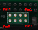
|
| 2 | VCC | +3.3V Power | P5-02 | 3V3 | |
| 3 | SCL | Clock | P5-04 | GPIO 29 (SCL) | |
| 4 | SDA | Data | P5-03 | GPIO 28 (SDA) |
Ensure that the I2C kernel driver is enabled:
$ dmesg | grep i2c
[    4.925554] bcm2708_i2c 20804000.i2c: BSC1 Controller at 0x20804000 (irq 79) (baudrate 100000)
[    4.929325] i2c /dev entries driver
or:
$ lsmod | grep i2c
i2c_dev                 5769  0
i2c_bcm2708             4943  0
regmap_i2c              1661  3 snd_soc_pcm512x,snd_soc_wm8804,snd_soc_core
If you have no kernel modules listed and nothing is showing using dmesg
then this implies the kernel I2C driver is not loaded. Enable the I2C as
follows:
$ sudo raspi-config
> Advanced Options > A7 I2C
After rebooting re-check that the dmesg | grep i2c command shows whether
I2C driver is loaded before proceeding. You can also
enable I2C manually if the
raspi-config utility is not available.
Optionally, to improve performance, increase the I2C baudrate from the default
of 100KHz to 400KHz by altering /boot/config.txt to include:
dtparam=i2c_arm=on,i2c_baudrate=400000
Then reboot.
Next, add your user to the i2c group and install i2c-tools:
$ sudo usermod -a -G i2c pi
$ sudo apt-get install i2c-tools
Logout and in again so that the group membership permissions take effect, and then check that the device is communicating properly (if using a rev.1 board, use 0 for the bus, not 1):
$ i2cdetect -y 1
       0  1  2  3  4  5  6  7  8  9  a  b  c  d  e  f
  00:          -- -- -- -- -- -- -- -- -- -- -- -- --
  10: -- -- -- -- -- -- -- -- -- -- -- -- -- -- -- --
  20: -- -- -- -- -- -- -- -- -- -- -- -- -- -- -- --
  30: -- -- -- -- -- -- -- -- -- -- -- UU 3c -- -- --
  40: -- -- -- -- -- -- -- -- -- -- -- -- -- -- -- --
  50: -- -- -- -- -- -- -- -- -- -- -- -- -- -- -- --
  60: -- -- -- -- -- -- -- -- -- -- -- -- -- -- -- --
  70: -- -- -- -- -- -- -- --
According to the man-page, “UU” means that probing was skipped, because the address was in use by a driver. It suggest that there is a chip at that address. Indeed the documentation for the device indicates it uses two addresses.
SPI
The GPIO pins used for this SPI connection are the same for all versions of the Raspberry Pi, up to and including the Raspberry Pi 3 B.
| OLED Pin | Name | Remarks | RPi Pin | RPi Function |
|---|---|---|---|---|
| 1 | VCC | +3.3V Power | P01-17 | 3V3 |
| 2 | GND | Ground | P01-20 | GND |
| 3 | D0 | Clock | P01-23 | GPIO 11 (SCLK) |
| 4 | D1 | MOSI | P01-19 | GPIO 10 (MOSI) |
| 5 | RST | Reset | P01-22 | GPIO 25 |
| 6 | DC | Data/Command | P01-18 | GPIO 24 |
| 7 | CS | Chip Select | P01-24 | GPIO 8 (CE0) |
Note
- When using the 4-wire SPI connection, Data/Command is an “out of band” signal that tells the controller if you’re sending commands or display data. This line is not a part of SPI and the library controls it with a separate GPIO pin. With 3-wire SPI and I2C, the Data/Command signal is sent “in band”.
- If you’re already using the listed GPIO pins for Data/Command and/or Reset,
you can select other pins and pass a
bcm_DCand/or abcm_RSTargument specifying the new BCM pin numbers in your serial interface create call. - The use of the terms 4-wire and 3-wire SPI are a bit confusing because, in most SPI documentation, the terms are used to describe the regular 4-wire configuration of SPI and a 3-wire mode where the input and output lines, MOSI and MISO, have been combined into a single line called SISO. However, in the context of these OLED controllers, 4-wire means MOSI + Data/Command and 3-wire means Data/Command sent as an extra bit over MOSI.
- Because CS is connected to CE0, the display is available on SPI port 0. You
can connect it to CE1 to have it available on port 1. If so, pass
port=1in your serial interface create call.
Enable the SPI port:
$ sudo raspi-config
> Advanced Options > A6 SPI
If raspi-config is not available, enabling the SPI port can be done
manually.
Ensure that the SPI kernel driver is enabled:
$ ls -l /dev/spi*
crw-rw---- 1 root spi 153, 0 Nov 25 08:32 /dev/spidev0.0
crw-rw---- 1 root spi 153, 1 Nov 25 08:32 /dev/spidev0.1
or:
$ lsmod | grep spi
spi_bcm2835             6678  0
Then add your user to the spi and gpio groups:
$ sudo usermod -a G spi pi
$ sudo usermod -a G gpio pi
Log out and back in again to ensure that the group permissions are applied successfully.