Hardware
It is essential that you get your device correctly wired to your single-board computer (SBC). The needed connections vary based upon the type of interface your device supports. There three major styles of interfaces that are popular with small LCD displays. These include I2C, SPI and 6800 style parallel-bus interfaces.
I2C vs. SPI vs Parallel
If you have not yet purchased your display, you may be wondering if you should get an I2C, SPI or parallel-bus display. The basic trade-off is implementation complexity and speed. The I2C is the easiest to connect because it has fewer pins while SPI may have a faster display update rate due to running at a higher frequency and having less overhead. Parallel-bus displays are both slower and harder to connect but are typically less expensive.
Identifying your interface
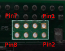
You can determine if you have an I2C, SPI or parallel-bus interface by counting the number of pins on your card. An I2C display will have 4 pins while an SPI interface will have 6 or 7 pins, and a parallel-bus interface will typically need to have at least 9 pins connected on a device but can requires 16 or more depending on the size of the bus and what other signals are required.
If you have a SPI display, check the back of your display for a configuration such as this:
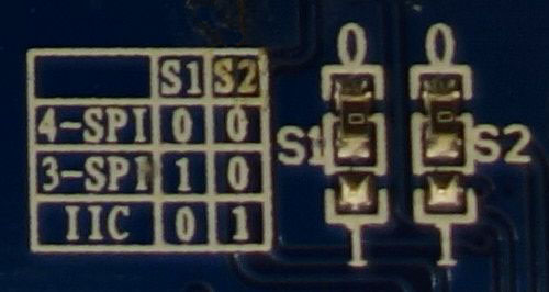
For this display, the two 0 Ohm (jumper) resistors have been connected to “0” and the table shows that “0 0” is 4-wire SPI. That is the type of connection that is currently supported by the SPI mode of this library.
Tip
If you don’t want to solder directly on the Pi, get 2.54mm 40 pin female single row headers, cut them to length, push them onto the Pi pins, then solder wires to the headers.
If you need to remove existing pins to connect wires, be careful to heat each pin thoroughly, or circuit board traces may be broken.
Triple check your connections. In particular, do not reverse VCC and GND.
I2C
I2C interfaces are the simplest to wire as they contain the smallest number of pins. The only signal lines are serial data (SDA) and serial clock (SCL). That plus the power and ground connections complete the required connections.
If you are using a Raspberry Pi you will normally attach to header P1. The P1 header pins should be connected as follows:
Device Pin |
Name |
Remarks |
RPi Pin |
RPi Function |
|---|---|---|---|---|
1 |
GND |
Ground |
P01-6 |
GND |
2 |
VCC |
+3.3V Power |
P01-1 |
3V3 |
3 |
SCL |
Clock |
P01-5 |
GPIO 3 (SCL) |
4 |
SDA |
Data |
P01-3 |
GPIO 2 (SDA) |
See also
Alternatively, on rev.2 RPi’s, right next to the male pins of the P1 header, there is a bare P5 header which features I2C channel 0, although this doesn’t appear to be initially enabled and may be configured for use with the Camera module.
Device Pin |
Name |
Remarks |
RPi Pin |
RPi Function |
Location |
|---|---|---|---|---|---|
1 |
GND |
Ground |
P5-07 |
GND |
|
2 |
VCC |
+3.3V Power |
P5-02 |
3V3 |
|
3 |
SCL |
Clock |
P5-04 |
GPIO 29 (SCL) |
|
4 |
SDA |
Data |
P5-03 |
GPIO 28 (SDA) |
Enabling The I2C Interface
The I2C interface may not be enabled by default on your SBC. To check if it is enabled:
$ dmesg | grep i2c
[    4.925554] bcm2708_i2c 20804000.i2c: BSC1 Controller at 0x20804000 (irq 79) (baudrate 100000)
[    4.929325] i2c /dev entries driver
or:
$ lsmod | grep i2c
i2c_dev                 5769  0
i2c_bcm2708             4943  0
regmap_i2c              1661  3 snd_soc_pcm512x,snd_soc_wm8804,snd_soc_core
If you have no kernel modules listed and nothing is showing using dmesg
then this implies the kernel I2C driver is not loaded.
For Raspberry Pi OS, enable the I2C driver as follows:
Run
sudo raspi-configUse the down arrow to select
Interface OptionsArrow down to
I2CSelect yes when it asks you to enable I2C
Also select yes when it asks about automatically loading the kernel module
Use the right arrow to select the <Finish> button
After rebooting re-check that the dmesg | grep i2c command shows whether
I2C driver is loaded before proceeding. You can also
enable I2C manually if the
raspi-config utility is not available.
Optionally, to improve performance, increase the I2C baudrate from the default
of 100KHz to 400KHz by altering /boot/config.txt to include:
dtparam=i2c_arm=on,i2c_baudrate=400000
Then reboot.
Next, add your user to the i2c group and install i2c-tools:
$ sudo usermod -a -G i2c pi
$ sudo apt-get install i2c-tools
Logout and in again so that the group membership permissions take effect
Determining Address
Check that the device is communicating properly (if using a rev.1 board,
use 0 for the bus, not 1) and determine its address using i2cdetect:
$ i2cdetect -y 1
       0  1  2  3  4  5  6  7  8  9  a  b  c  d  e  f
  00:          -- -- -- -- -- -- -- -- -- -- -- -- --
  10: -- -- -- -- -- -- -- -- -- -- -- -- -- -- -- --
  20: -- -- -- -- -- -- -- -- -- -- -- -- -- -- -- --
  30: -- -- -- -- -- -- -- -- -- -- -- -- 3c -- -- --
  40: -- -- -- -- -- -- -- -- -- -- -- -- -- -- -- --
  50: -- -- -- -- -- -- -- -- -- -- -- -- -- -- -- --
  60: -- -- -- -- -- -- -- -- -- -- -- -- -- -- -- --
  70: -- -- -- -- -- -- -- --
The address for your device will be needed when you initialize the interface. In the example above, the display address is 0x3c. Keep in mind that I2C buses can have more than one device attached. If more than one address is shown when you run i2cdetect, you will need to determine which one is associated with your display. Typically displays will only support a limited set of possible addresses (often just one). Checking the documentation can help determine which device is which.
SPI
The GPIO pins used for this SPI connection are the same for all versions of the Raspberry Pi.
Warning
There appears to be varying pin-out configurations on different display modules! Make sure to verify the pin numbers of your device by their function especially VCC and GND.
Device Pin |
Name |
Remarks |
RPi Pin |
RPi Function |
|---|---|---|---|---|
1 |
VCC |
+3.3V Power |
P01-17 |
3V3 |
2 |
GND |
Ground |
P01-20 |
GND |
3 |
D0 |
Clock |
P01-23 |
GPIO 11 (SCLK) |
4 |
D1 |
MOSI |
P01-19 |
GPIO 10 (MOSI) |
5 |
RST |
Reset |
P01-22 |
GPIO 25 |
6 |
DC |
Data/Command |
P01-18 |
GPIO 24 |
7 |
CS |
Chip Select |
P01-24 |
GPIO 8 (CE0) |
Note
If you’re already using the listed GPIO pins for Data/Command and/or Reset, you can select other pins and pass
gpio_DCand/orgpio_RSTargument specifying the new GPIO pin numbers in your serial interface create call (this applies to PCD8544, ST7567 and ST7735).Because CE is connected to CE0, the display is available on SPI port 0. You can connect it to CE1 to have it available on port 1. If so, pass
port=1in your serial interface create call.When using the 4-wire SPI connection, Data/Command is an “out of band” signal that tells the controller if you’re sending commands or display data. This line is not a part of SPI and the library controls it with a separate GPIO pin. With 3-wire SPI and I2C, the Data/Command signal is sent “in band”.
If you’re already using the listed GPIO pins for Data/Command and/or Reset, you can select other pins and pass a
gpio_DCand/or agpio_RSTargument specifying the new BCM pin numbers in your serial interface create call.The use of the terms 4-wire and 3-wire SPI are a bit confusing because in most SPI documentation, the terms are used to describe the regular 4-wire configuration of SPI and a 3-wire mode where the input and output lines, MOSI and MISO, have been combined into a single line called SISO. However, in the context of these OLED controllers, 4-wire means MOSI + Data/Command and 3-wire means Data/Command sent as an extra bit over MOSI.
Enabling The SPI Interface
To enable the SPI port in the Raspberry Pi OS:
$ sudo raspi-config
> Interface Options > SPI
If raspi-config is not available, enabling the SPI port can be done
manually.
Ensure that the SPI kernel driver is enabled:
$ ls -l /dev/spi*
crw-rw---- 1 root spi 153, 0 Nov 25 08:32 /dev/spidev0.0
crw-rw---- 1 root spi 153, 1 Nov 25 08:32 /dev/spidev0.1
or:
$ lsmod | grep spi
spi_bcm2835             6678  0
Then add your user to the spi and gpio groups:
$ sudo usermod -a -G spi,gpio pi
Log out and back in again to ensure that the group permissions are applied successfully.
Parallel
Beyond the power and ground connections, you can choose which ever GPIO pins you like to connect up your display. The following is one example for how to wire popular displays such as the Winstar WEH001602A.
Device Pin |
Name |
Remarks |
RPi Pin |
RPi Function |
|---|---|---|---|---|
1 |
GND |
Ground |
P01-6 |
GND |
2 |
VDD |
+5.0V Power |
P01-2 |
5V Power |
3 |
NC |
Not Connect |
||
4 |
RS |
Register Select |
P01-26 |
GPIO 7 |
5 |
R/W |
Read/Write |
P01-14 |
GND |
6 |
E |
Enable |
P01-24 |
GPIO 8 |
7 |
D0 |
Not Connected |
||
8 |
D1 |
Not Connected |
||
9 |
D2 |
Not Connected |
||
10 |
D3 |
Not Connected |
||
11 |
D4 |
Databus line 4 |
P01-22 |
GPIO 25 |
12 |
D5 |
Databus line 5 |
P01-18 |
GPIO 24 |
13 |
D6 |
Databus line 6 |
P01-16 |
GPIO 23 |
14 |
D7 |
Databus line 7 |
P01-13 |
GPIO 27 |
15 |
NC |
Not Connect |
||
16 |
NC |
Not Connect |
Note
You have the choice on whether to wire your device with 4 or 8 data-lines. Wiring with 8 provides a faster interface but at the cost of increased wiring complexity. Most implementations use 4 data-lines which provides acceptable performance and is the default setting for the parallel class.
Reading from the display is not supported by the
luma.core.interface.parallel.bitbang_6800class so it needs to be connected to ground in order to always be set for writes (assuming the device uses logic-low for write).
Warning
Be careful with the logic level of the device you are using. Many SBCs including the Raspberry Pi uses 3.3V logic. If your device supplies 5V to one of the GPIO pins of an SBC that uses 3.3V logic, you may damage your SBC.